What Is Welding Deformation in Thin Walled Plastic Parts?

Time:2026-10-07 Author:Sophia
0%

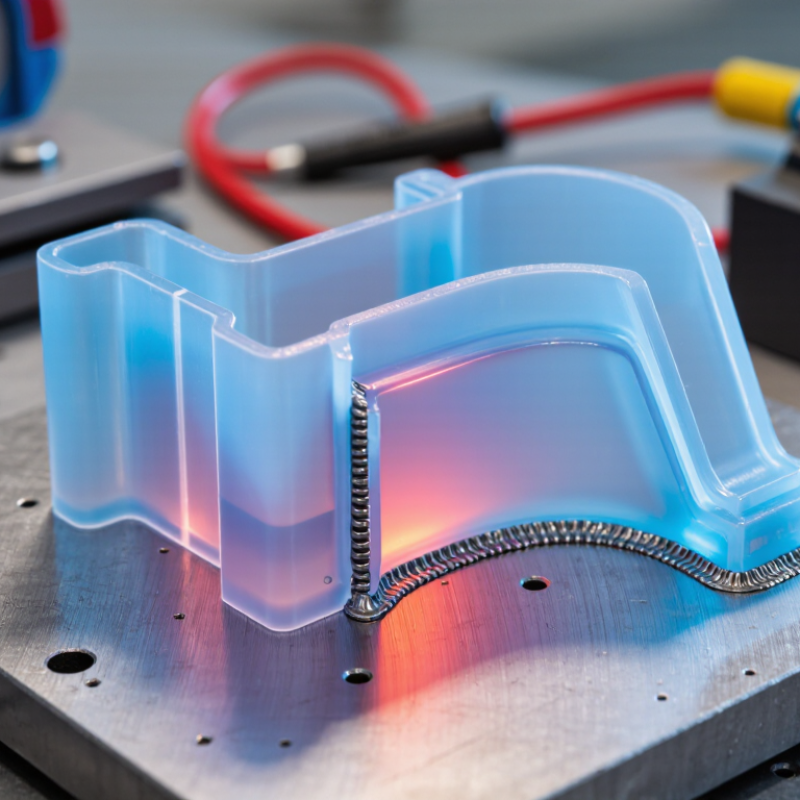
Thin-walled plastic parts can look simple, yet welding may quietly change their geometry. A 1.5-millimeter wall can bow beside a hot joint, leaving a visible step after cooling. This deformation comes from uneven heat, localized pressure, material shrinkage, and restrained movement. It affects sealing, assembly alignment, surface appearance, and long-term reliability.

The scale matters. PlasticsEurope’s Plastics—The Fast Facts 2024 reports global plastics production reached approximately 414 million tonnes in 2023. Even a small defect rate can therefore create substantial material waste and rework. The report also highlights continued pressure for efficient, resource-conscious manufacturing. That pressure makes process stability more important than simply increasing welding speed. Dr. David Grewell, a recognized plastics-joining researcher, states: “Control heat, pressure, and cooling together; no single setting can prevent deformation.” His principle is practical, although real production often treats temperature as the only variable.

This article examines How to control welding deformation of thin-walled plastic parts through balanced energy input, accurate fixturing, controlled cooling, and suitable joint design. Operators should monitor actual interface temperature, not only machine display values. A flat fixture may still create stress. Clamping too tightly can preserve shape temporarily, then release hidden distortion later. Shorter heating cycles may reduce warpage, but they can also weaken molecular fusion. There is no universal setting. Trial welds, dimensional inspection, and process records remain essential. A perfect flatness target can be misleading when the part must function under assembly stress. Reliable control begins by measuring the deformation pattern, finding its thermal cause, and correcting the process rather than masking the symptom.

What Is Welding Deformation in Thin Walled Plastic Parts?

Definition of Welding Deformation in Thin-Walled Plastic Parts

What Is Welding Deformation in Thin Walled Plastic Parts?

Definition of Welding Deformation in Thin-Walled Plastic Parts

Welding deformation is an unwanted dimensional change after joining thin plastic sections. The part may bend, twist, sink, or show a visible mismatch. This change usually comes from uneven heating and cooling. Residual stress can also pull the wall out of shape. Thin walls resist bending poorly, so small temperature differences can create noticeable distortion.

The problem often appears around weld lines, corners, ribs, and clamping points. I have seen a flat panel become slightly bowed after cooling. It passed a basic visual check, but failed assembly. That detail matters. According to the OECD’s Global Plastics Outlook, global plastic waste reached 353 million tonnes in 2019. This figure is not a welding statistic, but it highlights the cost of rework and rejected parts. ISO 21307 also emphasizes controlled heating, joining, and cooling for thermoplastic fusion processes. Still, real production is less tidy than a standard suggests.

Tips: Measure the part after full cooling. Check warpage in at least three directions. Reduce excessive clamp pressure. Keep energy distribution even. Record wall thickness, weld time, temperature, and cooling time. A laser scan can reveal gradual bowing that a ruler misses. Do not trust one perfect sample. It may hide unstable process conditions.

Common Causes of Deformation During Plastic Welding

What Is Welding Deformation in Thin Walled Plastic Parts?

Thin-walled plastic parts deform when welding heat, pressure, and cooling are uneven. The softened joint may shrink, buckle, or pull nearby walls inward. This problem appears often in ultrasonic, vibration, hot-plate, and laser welding. A narrow rib can tilt visibly after only a few seconds. The ASM Handbook, Volume 18, reports thermal expansion ranges of roughly 50–200 × 10⁻⁶/°C for many thermoplastics. That movement becomes significant across long, thin sections.

Common Causes of Deformation During Plastic Welding

Excessive weld energy is a common cause. It creates a larger molten zone and stronger residual stress. Unequal clamping pressure can also distort the part before cooling finishes. Poorly supported corners are especially vulnerable. Moisture, inconsistent wall thickness, and molded-in stress add further movement. ISO 294-4 identifies molding shrinkage as a key dimensional factor, often reaching several tenths of one percent in molded plastics. That small value can shift a tight seal or misalign a housing. In practice, engineers sometimes blame the welding machine too quickly. The fixture may be the real problem.

Tips: Use a rigid, low-friction fixture with support near the weld line. Reduce energy gradually during trials. Measure flatness at room temperature, not immediately after welding. Record part moisture and wall thickness. A thermal camera can reveal hot spots, but it cannot replace dimensional checks. I would also challenge “perfect” settings; minor material variation still matters.

How Welding Deformation Develops Step by Step

What Is Welding Deformation in Thin Walled Plastic Parts?

How Welding Deformation Develops Step by Step

Welding deformation begins with uneven heat, pressure, and cooling. In a thin plastic wall, heat travels quickly through a small section. The softened zone expands first. Then, the surrounding material restrains it. Internal stress starts building.

During ultrasonic or hot-plate welding, clamping force can also bend the part. A wall may tilt slightly while the joint is still soft. After cooling, the polymer contracts and locks that angle in place. The result may appear as a warped flange, oval opening, or stepped seam. It can be only 0.2 millimeters at first. That small shift can prevent proper assembly.

Material behavior matters. The PlasticsEurope Plastics—The Facts 2024 report states that global plastics production reached 413.8 million tonnes in 2023. This scale reflects wide material variation, not uniform performance. ASTM D955 identifies mold-shrinkage measurement as a key method for comparing plastic contraction. Engineers should test the actual resin, wall thickness, and welding cycle together.

The process is rarely perfect. A temperature setting that works on one cavity may fail on another. In production reviews, technicians should measure deformation before adjusting machine force. Check four points around the joint. Record temperature, pressure, hold time, and cooling time. Then compare the readings with the drawing tolerance. Skipping one variable can create a false solution.

What Is Welding Deformation in Thin-Walled Plastic Parts? — How Welding Deformation Develops Step by Step
Step Thermal or Mechanical Event How Deformation Develops Typical Observable Result Main Factors Increasing the Risk Practical Control Measures
1 Parts are positioned and clamped before welding. Uneven support or excessive clamping can introduce initial stress into a thin wall before heat is applied. Misalignment, local gaps, wall flattening, or a part that is already slightly bowed. Flexible geometry, unsupported spans, uneven fixtures, excessive clamp force, and dimensional variation between parts. Use full-surface support where possible, control clamp force, verify the initial fit, and avoid forcing the parts into alignment.
2 Heat is introduced at the weld interface by vibration, a heated tool, infrared radiation, laser energy, or another welding method. The weld zone expands as its temperature rises. Because the surrounding plastic is cooler and stiffer, thermal expansion is restrained and internal stress begins to build. Small local bulges, softening, gloss changes, or movement of the wall near the joint. High heat input, concentrated heating, long heating time, poor heat distribution, and low wall stiffness. Use a validated heat or energy setting, keep the interface uniformly engaged, and avoid concentrating heat outside the intended weld area.
3 The plastic reaches its softening or melting condition and a weld bead or molten layer forms. Softened material loses much of its load-bearing stiffness. Pressure, gravity, and fixture forces can then change the wall shape more easily. Wall indentation, local collapse, excessive bead formation, or material squeezed away from the joint. Excessive pressure, excessive displacement, insufficient support, high melt volume, and thin sections with low bending stiffness. Control weld pressure and collapse distance, support the wall close to the joint, and set energy input according to material and joint design.
4 Molten material flows while the parts are compressed or moved relative to each other. Material flow can be asymmetric. One side may experience more displacement, friction, or pressure, creating an uneven weld bead and an unbalanced force field. Offset joint lines, uneven bead width, corner distortion, or a slight twist along the weld path. Unequal part stiffness, nonparallel surfaces, inconsistent contact pressure, misalignment, and variable friction. Improve joint alignment, maintain parallel contact surfaces, balance fixture support, and use a joint design that guides material flow consistently.
5 Heating stops and the joint begins to cool under pressure. The weld zone contracts as it cools. The cooler surrounding material restricts this contraction, leaving residual stress and sometimes pulling the thin wall toward the joint. Post-weld bowing, sink-like areas near the weld, flange pull-in, or a change in flatness after release. Rapid or uneven cooling, large temperature gradients, thick-to-thin transitions, sharp corners, and insufficient hold time. Maintain stable holding pressure during solidification, allow adequate cooling before release, and reduce abrupt section changes in the design.
6 The fixture is released after the joint has partially or fully solidified. Elastic recovery and the release of residual thermal stress can cause the part to spring back into a different shape. Sudden dimensional shift, opened gaps, angular change, or a part that no longer meets the fixture datum. Early demolding, excessive clamping, high residual stress, poor datum control, and insufficient cooling uniformity. Define a consistent release temperature or cooling time, use repeatable datums, and measure parts after thermal stabilization.
7 The welded part continues to equilibrate at room temperature and may undergo post-weld stress relaxation. Residual stresses gradually redistribute. The final shape may differ from the shape observed immediately after welding. Delayed warpage, dimensional drift, long-term twisting, or a gradual change in flatness. Residual stress, anisotropic molecular orientation, uneven wall thickness, environmental temperature changes, and moisture-sensitive materials. Inspect after a defined conditioning period, control storage conditions, and evaluate the complete assembly rather than only the freshly welded part.
8 Deformation is evaluated against functional and visual requirements. Not every shape change is a failure. The critical issue is whether deformation affects sealing, fit, strength, appearance, or dimensional tolerances. Rejectable leakage, interference during assembly, reduced weld area, cosmetic distortion, or acceptable nonfunctional warpage. Unclear specifications, inconsistent measurement location, unsuitable gauges, and failure to distinguish local variation from functional failure. Set measurable limits for flatness, angle, gap, bead size, and leakage; use the same measurement method and stabilized inspection conditions.
Key principle: Welding deformation in thin-walled plastic parts is mainly produced by the interaction of thermal expansion, molten-material flow, applied pressure, cooling contraction, residual stress, and the low bending stiffness of thin walls. The most effective solution is usually a balanced combination of joint design, uniform support, controlled heat input, controlled pressure, and sufficient cooling before release.

Methods for Measuring and Evaluating Part Distortion

What Is Welding Deformation in Thin Walled Plastic Parts?

Methods for Measuring and Evaluating Part Distortion

Welding deformation is a visible change in shape after heat or vibration joining. Thin plastic walls may bow, twist, or sink near the weld line. Measure the part only after it reaches room temperature. Temperature can change plastic dimensions noticeably. Use stable datum points from the drawing, then record free-state measurements without clamping. A coordinate measuring machine, optical scanner, or dial indicator can capture different distortion patterns. For small parts, a height gauge and granite surface plate may be sufficient.

Compare the measured surface with the nominal CAD model. Check maximum deviation, flatness, wall angle, and hole position. A color map shows where the part moves, while cross-sections reveal local warpage near weld energy paths. Repeat each measurement several times. One scan can look convincing but still hide fixture influence. Evaluate both free-state and assembled conditions. A part may meet a flatness limit alone, yet fail when screws or neighboring parts apply load. This is where many evaluations become too simple.

Tips: Clean the part before measurement. Remove flash carefully. Do not force a warped edge into position. Record material lot, weld settings, cooling time, and measurement temperature. Use the same datums every time. A short inspection record improves comparison between trials. It is also worth reviewing the method itself. Some distortion may come from uneven cooling, not welding energy. That distinction is easy to miss.

Ways to Prevent and Control Welding Deformation

What Is Welding Deformation in Thin Walled Plastic Parts?

Ways to Prevent and Control Welding Deformation

Welding deformation occurs when heat softens a thin plastic wall unevenly. One side expands, while the cooler side resists movement. After cooling, the part may show warping, sink marks, tilted edges, or a distorted sealing surface. I have seen a flange twist slightly after removal from the fixture. It looked acceptable at first. Measurement later showed a leak risk.

Control begins with balanced heating and stable support. Keep the energy level only as high as the joint requires. Excessive heat enlarges the softened zone and increases shrinkage. Use a fixture that supports the wall close to the weld, without crushing it. Soft contact pads can prevent pressure marks. Preheating the surrounding area may reduce a sharp temperature difference. However, too much preheating can deform the entire part.

Joint design also matters. A wider, uniform welding bead distributes stress more evenly. Avoid sudden thickness changes near the weld. Allow the part to cool while clamped, but check whether the fixture blocks natural contraction. This is often overlooked. Record weld temperature, pressure, time, and cooling duration for each trial. Inspect several parts, not just the best sample. A process that works on a warm afternoon may shift in a colder workshop. If deformation remains, reduce heat input before increasing clamping force. Stronger clamping can hide the problem temporarily and create new stress.

FAQS

What is welding deformation in thin-walled plastic parts?

It is an unwanted dimensional change after joining thin plastic sections. Walls may bend, twist, sink, or misalign.

Why does welding deformation happen?

Uneven heating makes one side expand more than the other. Cooling then creates shrinkage and residual stress.

Which areas are most vulnerable to deformation?

Check weld lines, corners, ribs, flanges, and clamping points. These areas often show warping first.

How can deformation be measured accurately?

Measure the part after complete cooling. Check at least three directions, not only one flat edge.

Can a simple ruler detect every problem?

No. A ruler may miss gradual bowing across a wide panel. Laser scanning can reveal subtle shape changes.

How should fixtures support thin plastic walls?

Support the wall close to the weld without crushing it. Soft pads can reduce pressure marks and local stress.

Does using more clamping force solve deformation?

Not reliably. Strong clamping may hide movement temporarily, then release stored stress later. I would test heat reduction first.

How can the welding process become more stable?

Record temperature, pressure, weld time, wall thickness, and cooling duration. Inspect several parts from different workshop conditions.

Should the part cool while clamped?

Usually, controlled clamping can limit movement during cooling. However, the fixture must allow natural contraction.

What design changes can reduce warping?

Use a wider, even weld bead and avoid sudden thickness changes. Keep nearby ribs and corners from creating heat concentration.

Conclusion

Welding deformation in thin-walled plastic parts refers to unwanted bending, warping, shrinkage, twisting, or dimensional change that occurs during or after the welding process. Because thin walls have limited stiffness, they are especially sensitive to uneven heating, excessive welding energy, internal stress, poor joint design, inaccurate fixturing, and inconsistent cooling. Deformation usually develops when heat softens the weld area, the material expands, and then contracts unevenly as it cools. This imbalance can gradually pull the part out of its intended shape.

To evaluate distortion, manufacturers can compare critical dimensions with design specifications, inspect flatness and alignment, use gauges or coordinate measurement equipment, and check joint appearance and sealing performance. How to control welding deformation of thin-walled plastic parts depends on managing heat input, optimizing welding parameters, designing balanced joints, supporting the part securely, and allowing controlled cooling. Proper material selection, uniform wall thickness, accurate tooling, staged welding, and process monitoring can further reduce deformation and improve dimensional stability.

Sophia

Sophia

Sophia is a dedicated marketing professional with an exceptional depth of knowledge about her company's products and services. With a keen understanding of market trends and customer needs, she crafts insightful blog posts that not only inform but also engage readers, enriching the company’s online......