Choosing the right plastic joining method is rarely a simple contest. Spin welding and ultrasonic welding can both create strong, repeatable joints. However, they behave differently when materials, geometry, and production targets change. This article explores How to choose between spin welding and ultrasonic welding without relying on machine brochures alone.
Dr. Volker Schöppner, a respected plastics-joining researcher, offers a practical principle: “The joining process must serve the component’s function.” That idea matters on the factory floor. Spin welding suits round parts, such as tanks, filters, and cylindrical housings. The rotating interface generates frictional heat and can produce a visible bead or flash. Ultrasonic welding uses high-frequency vibration, making it useful for smaller parts, complex shapes, and short cycle times. Yet thin walls, poor energy-director design, or sensitive electronics can reduce its reliability.
A sound decision begins with trials, not assumptions. Engineers should compare weld strength, leakage, flash, cycle time, tooling cost, and operator consistency. Destructive testing can expose weak interfaces that look perfect from outside. That detail is easy to miss. Material moisture, clamping pressure, amplitude, rotational speed, and fixture alignment also influence results. Production volume changes the calculation, too. A low-volume part may tolerate slower spin welding, while a high-volume assembly may justify ultrasonic tooling. The answer is not always elegant. Sometimes the technically stronger process costs too much. Sometimes the cheaper process creates unacceptable cosmetic defects. Careful testing, documented settings, and supplier expertise provide the most dependable path forward.
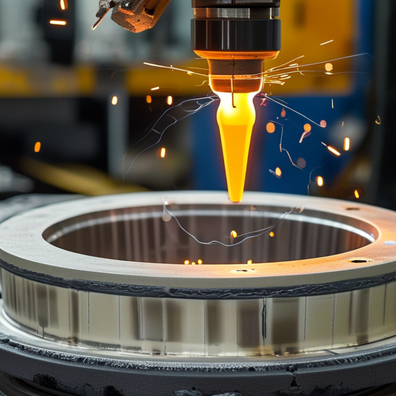
Spin welding creates a joint through frictional heat. One thermoplastic part rotates against another, commonly between 500 and 3,000 rpm. Pressure and rotation soften the interface, then the machine stops and holds the parts together. The process suits round components, such as caps, containers, filters, and pipe fittings. It is fast, mechanically simple, and often produces a visible melt bead.
Thermoplastic compatibility matters more than speed. Similar melting behavior usually gives a more stable bond. Materials with different softening ranges may separate, discolor, or develop weak areas. A practical setup needs controlled force, accurate alignment, and a clean joining surface. Even small eccentricity can create uneven heating. That detail is easy to underestimate.
Compared with ultrasonic welding, spin welding normally needs rotational geometry and a larger joining path. Ultrasonic welding can suit smaller, irregular parts, but it requires careful horn design and energy control. In workshop trials, I would inspect torque, axial force, bead size, and leak performance rather than trust appearance alone. The joint may look sound and still fail under pressure. A poor fixture can hide this problem. Process records should include rpm, weld time, hold time, and material lot. I would also test samples after aging, because fresh welds can seem stronger than they remain.
Spin welding and ultrasonic welding create heat in very different ways. Spin welding uses rotational friction across a circular joint. Ultrasonic welding uses 15–70 kHz vibrations, pressure, and controlled energy transfer. A horn presses the parts together while microscopic movement generates heat at the interface. The softened thermoplastic then bonds under continued pressure.
Frequency alone does not guarantee a strong weld. Joint geometry, material stiffness, amplitude, pressure, and delivered energy must remain balanced. In practical trials, I watch the joint line closely. A clean, narrow flash can indicate proper melting. Excessive flash may signal too much energy or pressure. A weak joint may come from poor alignment, not insufficient force. That distinction is easy to miss.
Spin welding often suits round components with continuous contact surfaces. Ultrasonic welding can fit smaller parts with precise, localized joints and short cycle times. However, thin walls, ribs, and uneven contact areas can absorb vibration before the interface melts. I have seen operators increase pressure to correct this issue. It sometimes makes the result worse. Engineers should measure weld strength, leakage, dimensional change, and cycle consistency across several energy settings. A reliable process window matters more than one successful sample.
| Comparison Dimension | Spin Welding | Ultrasonic Welding | Practical Implication |
|---|---|---|---|
| Primary energy source | Rotational friction between two thermoplastic components. | Mechanical vibration transmitted through a horn, combined with clamping pressure and interfacial friction. | Both processes convert mechanical energy into localized heat at the joint. |
| Operating frequency or motion | Continuous or controlled rotation; the process is generally specified by rotational speed, torque, and spin time rather than vibration frequency. | High-frequency vibration typically within the 15–70 kHz range; common industrial systems operate near 20, 30, 35, or 40 kHz. | Ultrasonic frequency affects amplitude, tooling design, cycle behavior, and suitable part size. |
| Joint geometry | Best suited to circular, annular, or rotationally symmetric joints. | Best suited to small, localized joints, including linear seams, ribs, bosses, and energy-director designs. | Choose spin welding when the joint can rotate; choose ultrasonic welding when localized access is more important than rotational symmetry. |
| Typical thermoplastic compatibility | Works well with many compatible thermoplastics that can generate and sustain frictional heat, including polyethylene, polypropylene, ABS, polycarbonate, and nylon grades. | Works well with many rigid thermoplastics, including ABS, polystyrene, polycarbonate, polypropylene, polyethylene, and selected nylon grades. | Material compatibility depends on melting behavior, stiffness, moisture, fillers, and the similarity of the mating materials. |
| Heat generation and energy transfer | Heat is generated over a comparatively broad annular interface through relative rotational motion, pressure, and frictional work. | Energy is concentrated at the contact interface through 15–70 kHz vibration, pressure, and controlled amplitude. | Ultrasonic welding generally offers more localized energy delivery; spin welding can distribute heat around a full circular joint. |
| Cycle time | Often measured in seconds; the actual time depends on joint diameter, frictional conditions, pressure, speed, and the required weld depth. | Often measured in fractions of a second to a few seconds for small assemblies, depending on material, joint design, amplitude, pressure, and hold time. | Ultrasonic welding is frequently advantageous for high-throughput small-part assembly, while both methods can support automated production. |
| Clamping and pressure | Requires axial force to maintain contact while rotation creates frictional heat and material displacement. | Requires fixture support and weld pressure to couple vibration into the parts and maintain contact during the weld and hold stages. | Poor force control can cause incomplete bonding, excessive flash, part deformation, or inconsistent weld depth. |
| Flash and particulate generation | Can produce a visible circumferential bead or flash from displaced molten material. | May produce limited flash or particulate, especially when the joint is poorly designed, overdriven, contaminated, or misaligned. | Ultrasonic welding is often preferred where a small weld footprint and low visible flash are important. |
| Tooling and fixture requirements | Needs a rotational drive, chuck or nest, axial-force system, and tooling that maintains concentricity. | Needs a transducer, booster, horn, weld fixture, and joint features designed for efficient vibration transfer. | Tooling cost and design complexity depend strongly on part geometry, production volume, and required tolerances. |
| Dimensional and cosmetic control | Can provide strong circumferential joints, but weld collapse, flash, and rotational alignment must be controlled. | Can provide repeatable weld collapse and short cycle times when the horn, fixture, amplitude, and energy-director geometry are correctly matched. | Ultrasonic welding is often better for small precision features; spin welding is effective for robust circular assemblies. |
| Sealing performance | Can produce continuous, hermetic-capable circular seals when joint design, material compatibility, and process control are appropriate. | Can produce sealed joints when the weld path is continuous and the interface receives sufficient, uniform energy. | The sealing result depends more on joint design and process validation than on the process name alone. |
| Noise and vibration environment | Produces mechanical rotation and friction noise; guarding and balancing may be required at higher speeds. | May generate audible high-frequency noise and structural vibration; acoustic enclosures and hearing protection may be needed. | Workplace noise controls should be evaluated during equipment selection and process qualification. |
| Best-fit applications | Circular housings, caps, tanks, pipes, filters, and other rotationally symmetric thermoplastic parts. | Small housings, electrical and electronic assemblies, medical components, packaging parts, and localized plastic joints. | Part geometry is usually the first selection criterion, followed by material, cleanliness, cycle time, and appearance. |
| Overall selection guidance | Often the better choice for large-diameter or circular joints requiring a continuous circumferential weld. | Often the better choice for small, localized, clean, and fast welds where a 15–70 kHz vibration system can access the joint effectively. | Neither process is universally superior; validated joint design and process trials should determine the final choice. |
Note: The values and operating ranges shown are representative engineering guidance. Actual performance varies with polymer grade, part geometry, joint design, tooling, weld force, amplitude, rotational speed, and production requirements.
Spin welding and ultrasonic welding make different trade-offs in strength, cycle time, and energy use. Spin welding suits round parts with continuous, pressure-resistant joints. Technical guidance from the American Welding Society reports that friction-based plastic welds can approach the parent material’s strength when flash, pressure, and melt displacement are controlled. That control is not automatic. Poor alignment can create a weak ring or uneven wall thickness.
Ultrasonic welding usually offers shorter cycles. Process studies commonly report weld times between 0.1 and 1 second, while spin welding often takes 0.5 to 3 seconds, excluding loading and cooling. The difference becomes meaningful in high-volume production. However, ultrasonic results depend heavily on joint design, horn pressure, and material moisture. Small changes matter. A 2022 U.S. Department of Energy industrial energy assessment also stresses that connected motor power does not equal actual energy per part.
Measured energy use can therefore mislead. A spin welder may draw roughly 1–5 kW during acceleration, while an ultrasonic system may use about 0.5–3 kW during its brief weld pulse. In practice, both processes may consume only fractions of a watt-hour per part, depending on cycle settings and standby time. I would not select ultrasonic welding only because its cycle looks faster. The DOE’s Industrial Decarbonization Roadmap highlights idle energy and compressed-air losses, yet these are often ignored in factory comparisons. A joint-strength test aligned with ISO 19095 can expose another uncomfortable issue: the strongest sample may still hide inconsistent production.
Spin Welding vs Ultrasonic Welding: Which Is Better?
Material choice often decides the process before equipment settings do. Spin welding suits compatible thermoplastics that soften through rotational friction. It can create a wide, continuous joint around circular parts. Polyolefins and similar materials often respond well, but fillers may change heat flow and torque requirements. Ultrasonic welding uses high-frequency vibration and pressure. It works well with many rigid thermoplastics, especially when the joint includes a carefully designed energy director. Material pairing matters. Two plastics may look similar yet weld poorly together.
Part geometry can be more restrictive than expected. Spin welding needs a round or rotationally balanced interface. A small cap may weld evenly, while an oval housing can develop uneven heating and visible flash. Ultrasonic welding handles smaller joints and complex profiles better. However, ribs, deep cavities, and flexible walls can absorb vibration before the joint seals. I have seen a strong-looking horn mark a part without producing a reliable weld. That result was not a machine failure. The geometry was wrong.
Tolerance limits should guide the decision early. Spin welding can tolerate some variation in circular alignment, but excessive runout affects friction and seal width. Ultrasonic welding demands controlled joint height, contact pressure, and fixture support. A few tenths of a millimeter may change collapse distance and strength. Prototype testing should measure burst strength, leak rate, flash, and cosmetic damage. One test is not enough. Real production parts vary, and early samples can hide that weakness.
Spin Welding vs Ultrasonic Welding: Which Performs Better?
Safety, equipment cost, and production scale often decide between spin welding and ultrasonic welding. Spin welding uses frictional heat, so it suits round thermoplastic parts such as caps, filters, and housings. Its tooling is usually simpler and less expensive. However, rotating parts create pinch points and demand reliable guarding. Ultrasonic welding avoids large rotational motion and completes joints in milliseconds. It can improve operator safety, but high-frequency vibration, noise, and acoustic exposure still require controls. OSHA’s machine-guarding guidance supports physical barriers, interlocks, and documented risk assessments for both methods.
Production scale changes the calculation. Ultrasonic welding offers fast cycles and repeatable energy delivery for high-volume assemblies. Spin welding may perform better when components vary slightly or joint designs need stronger mechanical interference. The U.S. Department of Energy’s Industrial Decarbonization Roadmap identifies industrial process efficiency as a major emissions opportunity. Lower cycle energy matters, although actual savings depend on part geometry, cooling time, and rejected parts. Published supplier data often reports sub-second ultrasonic cycles, but real factory results can be slower after loading, inspection, and maintenance.
Tips: Measure the complete cycle, not only weld time. Compare tooling replacement, guarding, ventilation, training, and scrap. Run a pilot batch. One overlooked alignment issue can erase the apparent cost advantage. Record joint strength, noise readings, and defects across several shifts. Independent testing against ISO 21307 principles can strengthen process validation, even when the application is not conventional plastic pipe welding.
This comparative index summarizes common industrial characteristics on a 1–10 scale. Higher scores indicate a stronger advantage for the selected criterion. Actual results depend on material, joint design, component geometry, tooling, and production requirements.
: Spin welding joins thermoplastic parts through frictional heat. One part rotates against another, usually at 500–3,000 rpm. Pressure softens the interface, then the machine stops and holds the parts together.
Round or rotationally balanced parts work best. Suitable examples include caps, containers, filters, and pipe fittings. Oval housings may heat unevenly and create visible flash.
Compatible plastics usually soften within similar temperature ranges. Poorly matched materials may separate, discolor, or develop weak areas. Similar appearance does not guarantee good welding.
Alignment is critical. Small eccentricity can produce uneven heating and inconsistent seal width. A poor fixture may hide the problem during early testing.
No. A visible bead only shows that melting occurred. The joint may still leak or fail under pressure. Appearance can mislead.
Spin welding suits circular joints and creates a continuous joining path. Ultrasonic welding handles smaller or irregular profiles more effectively. However, it needs controlled vibration, pressure, and joint design.
Check torque, axial force, weld time, hold time, rpm, bead size, leakage, and burst strength. Record the material lot too. One test is not enough.
Excessive runout changes friction and seal width. Ultrasonic joints also depend on contact pressure, joint height, and fixture support. A few tenths of a millimeter may alter strength.
Yes. Fresh welds can appear stronger than they remain. Test samples after aging, pressure exposure, and normal production variation. That assumption can be wrong.
Spin welding and ultrasonic welding are both effective methods for joining thermoplastic components, but they rely on different forms of energy. Spin welding generates frictional heat by rotating one part against another, typically at 500–3,000 rpm, making it suitable for circular components and compatible thermoplastic materials. Ultrasonic welding uses vibrations between 15–70 kHz, combined with pressure, to create heat and bond parts quickly. The best choice depends on joint strength, cycle time, energy consumption, and production requirements.
How to choose between spin welding and ultrasonic welding depends on material type, part geometry, dimensional tolerances, and desired output. Spin welding can provide strong, continuous seals but may produce visible rotational marks or require precise alignment. Ultrasonic welding generally offers short cycles, low energy use, and clean operation, although it requires carefully designed joint features and stable tolerances. Equipment cost, operator safety, maintenance, and production scale should also be evaluated before selecting the process.

Heping Mechanical