How does high frequency induction welding improve metal joining quality? The answer begins with controlled energy, not simply higher power. High frequency current concentrates near the metal surface through the skin effect. This creates rapid, localized heating along the joint edges. The process can produce a narrow heat-affected zone, helping reduce distortion, oxidation, and unnecessary grain growth.
Dr. Valery Rudnev, a respected induction-heating authority and co-author of Handbook of Induction Heating, has stated, “Induction heating is a precise, controllable, and highly efficient process.” That principle explains why manufacturers use high frequency induction welding for tubes, pipes, automotive parts, and engineered assemblies. When frequency, coil geometry, line speed, and pressure are properly matched, the weld edges reach joining temperature evenly. The result can be a cleaner seam with consistent strength and repeatable dimensions.
But the technology is not automatically perfect. Poor coil alignment can create uneven heating. Excessive speed may leave an incomplete bond. Weak edge preparation can also undermine an otherwise stable process. These details matter on the factory floor, where a glowing seam, a small gap, or a slight vibration can change the final result. How does high frequency induction welding improve metal joining quality? It improves quality through concentrated heat, accurate process control, and disciplined inspection. Yet operators must still verify weld penetration, seam integrity, and dimensional stability. Efficiency helps, but careful measurement remains essential.
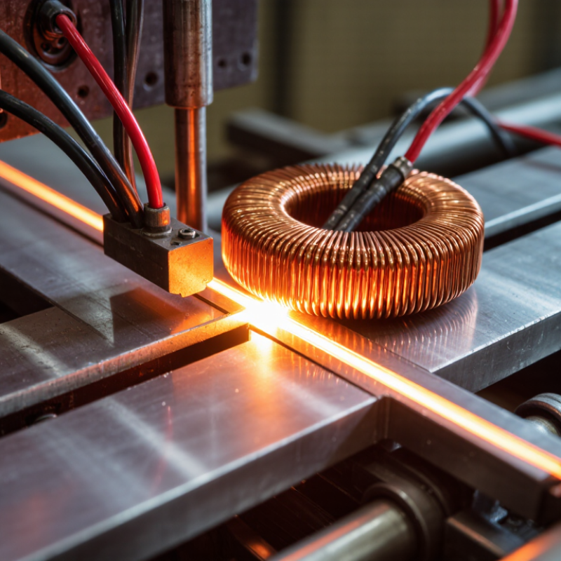
How High Frequency Induction Welding Improves Joining Quality?
High-frequency induction welding is a pressure welding process for electrically conductive materials. An alternating current flows through an induction coil surrounding the workpiece. This current creates a rapidly changing magnetic field. The field induces eddy currents near the material’s surface. These currents generate localized heat through electrical resistance.
The heated edges then move together under controlled pressure. They form a solid-state bond without melting the entire joint area. In tube production, the strip edges meet at a narrow V-shaped point. The frequency affects current penetration, heating speed, and energy concentration. The skin effect keeps most current near the surface. The proximity effect concentrates heat where the edges approach each other. Careful alignment matters.
Small changes can matter greatly. Material thickness, surface condition, line speed, coil position, and pressure influence the final weld. Experienced operators monitor temperature patterns, weld appearance, and process signals together. A stable process should produce a consistent seam, limited oxidation, and minimal internal defects. Visual inspection alone is not enough.
The theory appears clean. Factory conditions are not. Coil wear, uneven edges, or slight speed changes can disturb heat balance. A setting that worked yesterday may require adjustment today. That fact deserves attention, not denial. Reliable results come from measured parameters, sound maintenance, and testing that checks both the surface and the joint’s mechanical performance.
High-frequency induction welding begins with controlled material preparation. Tube edges must be clean, aligned, and evenly formed before heating starts. Even a small gap can disturb current flow and weaken the weld. The induction coil then creates a concentrated electromagnetic field near the joint. Heat develops rapidly at the edges, while surrounding steel remains comparatively cool. Production references commonly report line speeds between 30 and 120 metres per minute. That speed demands accurate setup, not guesswork.
The squeeze stage follows heating. Roll pressure forces the softened edges together and expels oxides from the weld zone. Operators monitor power, frequency, line speed, and pressure as one system. Changing only one setting can create hidden defects. Technical guidance from the Edison Welding Institute stresses stable impedance and consistent edge presentation for reliable high-frequency welding. The 2023 World Steel Association data recorded about 1.89 billion tonnes of crude steel production worldwide, reinforcing the need for repeatable joining methods.
Inspection completes the process. Non-destructive testing can identify cracks, lack of fusion, and edge defects without cutting every tube. Records should link test results with coil position, temperature, and production speed. That traceability supports corrective action. Still, induction welding is not automatically perfect. Surface scale, worn tooling, or poor cooling can quietly reduce quality. A practical review of the fracture surface often reveals more than a confident production assumption.
High frequency induction welding improves joint formation by directing heat toward the material edges. The skin effect keeps current near the surface, while the proximity effect concentrates it around the weld vee. At the interface.
This focused heating creates a narrow, controllable thermal zone. The edges reach forging temperature before squeeze rolls press them together. Oxides and unstable material can then move away from the joint. Proper pressure forms a continuous bond without heating the entire workpiece. This reduces distortion and supports faster production.
Consistency depends on more than frequency. Tube edge preparation, line speed, coil position, impedance, and squeeze pressure must work together. Experienced operators monitor temperature trends and inspect the weld bead regularly. Small alignment changes can alter current flow. Calibration also matters. A sensor may drift, and a stable-looking process may hide weak bonding.
In production, the first setup rarely performs perfectly. That is an important limitation. Excessive heat can enlarge the affected zone, while insufficient heat leaves an incomplete bond. Reviewing samples, adjusting parameters, and recording results help build a reliable process. Induction heating improves repeatability, but disciplined control creates the final joint quality.
How High Frequency Induction Welding Improves Joining Quality?
High frequency induction welding concentrates electrical current near the material surface. This effect heats the joint edge quickly and supports a narrow heat-affected zone. Frequency strongly influences heating depth. Higher frequencies usually heat thinner surface layers. Lower frequencies can reach deeper sections, but they may reduce control on thin materials. In production trials, I check temperature, weld speed, and edge alignment together. Frequency alone never guarantees a sound joint.
Power controls how quickly the material reaches its joining temperature. Excessive power can create burn-through, oxidation, or uneven bead formation. Insufficient power may leave cold spots and weak bonding. Material properties also matter. Electrical conductivity, magnetic behavior, thickness, and surface condition change the required settings. Two similar-looking metals may need different power levels. That detail is easy to underestimate. A clean, steady edge usually produces more consistent results than a higher power setting.
Tips: Begin with moderate frequency and power. Watch the weld seam continuously. Use sample sections before full production. Record temperature, speed, and visible defects. Small changes in coil distance can alter heating significantly. Keep the coil centered, but do not assume perfect alignment. Operators should inspect cross-sections, because a smooth surface can hide incomplete bonding. Some process adjustments may seem obvious, yet they still fail when material batches vary. That is why repeatable measurements remain more reliable than visual judgment alone.
Calculated electromagnetic skin depth at typical induction-welding frequencies. Smaller skin depth concentrates current nearer the surface, while electrical resistivity and magnetic permeability determine penetration behavior.
Skin depth is calculated using δ = √(ρ / πfμ), where ρ is electrical resistivity, f is frequency, and μ is magnetic permeability. Increasing frequency generally reduces penetration depth and can improve localized heating and seam control. Welding power determines the available heat input: insufficient power may cause incomplete bonding, while excessive power can produce overheating, expulsion, or distortion. Actual settings must be adjusted for geometry, surface condition, material temperature, and coil design.
Reference conditions: nominal room-temperature properties; copper ρ = 1.68 × 10⁻⁸ Ω·m, aluminum ρ = 2.82 × 10⁻⁸ Ω·m, austenitic stainless steel ρ = 7.20 × 10⁻⁷ Ω·m; relative permeability is approximated as 1 for these non-ferromagnetic materials.
How High Frequency Induction Welding Improves Joining Quality?
Inspection Methods for Evaluating Weld Strength and Reliability
High frequency induction welding concentrates heat at the strip edges, creating a narrow, fast-forming seam. That speed improves productivity, but it also reduces the time available for error detection. Inspection must therefore combine surface checks, process records, and destructive testing.
Visual inspection should examine bead shape, edge alignment, undercut, overheating, and expelled material. A calibrated camera can record the weld continuously. However, appearance alone cannot confirm internal bonding. ISO 17640 identifies four ultrasonic testing levels, allowing inspectors to adjust sensitivity and coverage for welded components. Ultrasonic testing can reveal lack of fusion, inclusions, and irregular seam geometry beneath the surface.
Eddy current testing is useful for rapid, non-contact monitoring on moving tube lines. It can identify cracks and conductivity changes near the weld. Operators should verify indications with ultrasonic testing or metallographic sections. Tensile, flattening, flaring, and bend tests then challenge the joint under realistic loads. ISO 11666 defines two ultrasonic acceptance levels, while ISO 15614-1 supports procedure qualification through documented mechanical testing.
Small details matter. Keep probe calibration records beside production data. Compare defect signals with line speed, pressure, and temperature. A clean scan can still mislead when coupling is poor or calibration drifts. That weakness deserves attention. Nondestructive testing also depends heavily on operator training, equipment setup, and consistent acceptance criteria. Independent review and periodic destructive sampling provide stronger evidence of weld reliability.
| Inspection Method | Primary Quality Dimension | Typical Measurement or Test Data | What the Result Indicates | Typical Application Frequency | Common Acceptance Considerations |
|---|---|---|---|---|---|
| Visual Inspection | Surface condition, weld bead profile, alignment, visible defects | Bead width: approximately 1.5–4.0 mm Visible undercut: ideally 0 mm Surface cracks: 0 permitted |
Identifies flash irregularities, surface cracking, excessive oxidation, misalignment, incomplete trimming, and mechanical damage. | 100% of production length or a continuous camera-based monitoring system | The weld should be continuous and free from visible cracks, open seams, harmful undercut, sharp notches, and excessive weld spatter. Final limits should follow the applicable product specification. |
| Dimensional and Alignment Inspection | Tube geometry, weld-line position, ovality, wall thickness, and joint alignment | Ovality commonly controlled within 1–2% of outside diameter Weld-line offset often controlled to less than 10% of wall thickness |
Confirms that forming and squeeze-roll conditions have produced a stable joint geometry suitable for downstream forming or service. | At setup, after tooling changes, and periodically during production | Permissible dimensional limits depend on tube size, wall thickness, material grade, and the relevant dimensional standard. |
| Macroetch Examination | Weld-zone penetration, fusion profile, inclusions, lack of bonding, and heat-affected-zone symmetry | Typical section thickness: 10–20 mm Typical examination magnification: 5×–20× |
Reveals internal weld morphology that cannot be confirmed reliably by surface inspection alone, including hook defects and incomplete edge fusion. | During process qualification, after major parameter changes, and for periodic production audits | The fusion line should be continuous and adequately bonded across the wall thickness. Defect limits are normally defined by the product or welding procedure specification. |
| Hardness Mapping | Heat-affected-zone behavior, local over-hardening, softening, and thermal uniformity | Vickers loads commonly used: HV0.5 or HV1 Measurements taken across the weld, HAZ, and base metal |
Highlights rapid thermal-cycle effects, unsuitable post-weld heat treatment, or local microstructural changes that may reduce toughness or formability. | Qualification testing and periodic verification; not usually a full-length production test | Hardness should remain within the specified material or procedure range and should not show an unexplained sharp peak or drop near the weld zone. |
| Transverse Tensile Test | Ultimate tensile strength, yield behavior, elongation, and fracture location | Reported values: yield strength, ultimate tensile strength, elongation, and fracture location Common specimen orientation: transverse to the weld |
Measures whether the welded joint can carry tensile load and whether failure occurs in the weld, HAZ, or unaffected base metal. | Procedure qualification, material validation, and scheduled destructive audits | Typical requirements include meeting the specified minimum strength and avoiding premature fracture through an incompletely fused weld zone. |
| Flattening or Crush Test | Ductility, weld integrity, and resistance to deformation | Tube flattened between parallel plates or compressed to a specified height Weld commonly positioned at 90° or 0° to the loading direction, depending on the procedure |
Exposes brittle welds, incomplete bonding, excessive local hardness, and defects that become critical during forming. | Qualification testing and routine sampling for welded tube products | No crack or opening should develop in the weld or HAZ before the specified deformation requirement is reached. |
| Guided Bend Test | Weld ductility, soundness, and resistance to cracking under bending strain | Common bend angles: 90° or 180° Typical former diameter: approximately 3–4 times specimen thickness, subject to the governing standard |
Detects lack of fusion, planar defects, excessive brittleness, and poor weld-zone ductility. | Procedure qualification, periodic destructive verification, and investigation of process deviations | Surface-breaking cracks beyond the permitted size or number are generally unacceptable; the applicable code defines the exact limit. |
| Ultrasonic Testing | Internal discontinuities, lack of fusion, planar defects, and bond continuity | Typical frequency range: 2–10 MHz Methods may include focused probes or phased-array systems |
Provides volumetric or near-line inspection of the weld without cutting the product, supporting continuous monitoring of production length. | 100% online inspection where equipment and product geometry permit | Indication amplitude, length, location, and repeatability are compared with calibrated reference reflectors and the applicable acceptance level. |
| Eddy Current Testing | Surface and near-surface cracks, seam discontinuities, and changes in electrical conductivity | Typical test frequency: approximately 100 kHz–2 MHz, selected according to material and wall thickness Calibration uses representative artificial flaws |
Detects short, tight, or surface-connected defects at production speed without contacting the material directly. | 100% online inspection is common for conductive tube and strip products | Alarm thresholds should be established using calibrated notches or reference defects and verified at startup and at defined intervals. |
| Pressure or Hydrostatic Test | Leak tightness and pressure boundary integrity | Test pressure and hold time are product-specific Common hold periods: 5–30 seconds after stabilization |
Confirms that the welded tube or component does not leak under the specified service or proof-pressure condition. | 100% testing for pressure-containing products when required by the design specification | No visible leakage, pressure loss beyond the allowed limit, or permanent deformation should occur during the specified test. |
| Helium or Air Leak Testing | Gas-tightness and very small leak detection | Helium leak limits commonly range from 10−5 to 10−3 mbar·L/s, depending on application Air-pressure limits are product-specific |
Provides greater sensitivity than a conventional hydrostatic test for sealed assemblies, refrigeration lines, heat exchangers, and high-integrity tubing. | 100% testing for critical sealed components; sampling for less critical products | The permitted leak rate must be defined by system function, internal pressure, fluid type, and safety requirements. |
| Metallographic Examination | Grain structure, oxide inclusions, martensite formation, recrystallization, and weld-zone microstructure | Typical polished-section magnification: 50×–500× Higher magnification may be used for inclusions or fine phases |
Explains the metallurgical causes of strength loss, cracking, poor toughness, or inconsistent forming performance. | Material qualification, failure analysis, and process development | The microstructure should be consistent with the qualified welding procedure and free from unacceptable oxide entrapment, cracks, or unbonded regions. |
| Process Parameter Monitoring | Thermal stability, energy input, squeeze force, line speed, and repeatability | Monitored variables may include welding power, frequency, line speed, coil position, squeeze-roll force, and upset/flash dimensions | Detects process drift before it becomes a finished-product defect and helps correlate inspection results with actual welding conditions. | Continuous monitoring with alarms and recorded trends | Control limits should be established during procedure qualification. A stable trend is generally more important than a single isolated reading. |
Note: The numerical values shown are representative engineering ranges for inspection planning, not universal acceptance criteria. Final limits should be established from the material grade, wall thickness, tube geometry, service conditions, qualified welding procedure, and applicable standards.
Tube edges should be clean, aligned, and evenly formed. Even a small gap can disturb current flow. Poor preparation may weaken the seam before heating begins.
The coil creates a concentrated electromagnetic field near the edges. Heat develops quickly at the joint. Surrounding steel usually stays comparatively cool.
Typical line speeds range from 30 to 120 metres per minute. Fast production requires accurate setup. Guesswork is risky.
These settings influence one another during welding. Changing one setting can create hidden defects. A stable process needs consistent edge presentation and impedance.
Higher frequencies usually heat thinner surface layers. Lower frequencies can reach deeper sections. Excessive power may cause burn-through or oxidation. Insufficient power can leave cold spots.
Not reliably. Conductivity, magnetic behavior, thickness, and surface condition affect heating. Similar-looking materials may need different settings. That detail is easy to miss.
Visual checks can identify bead shape, undercut, overheating, and alignment problems. Ultrasonic testing can detect incomplete fusion beneath the surface. Eddy current testing supports rapid monitoring on moving lines.
Tensile, flattening, flaring, and bend tests challenge the joint under practical loads. A clean scan can still mislead. Calibration, coupling, and operator skill affect inspection results.
Records should connect test results with coil position, temperature, speed, pressure, and calibration details. This supports corrective action. I would not trust appearance alone.
High-frequency induction welding is a controlled joining process that uses electromagnetic energy to generate heat directly within conductive materials. The induced current concentrates near the joint area, allowing surfaces to reach welding temperature quickly without heating the entire workpiece. The process typically includes surface preparation, precise alignment, coil positioning, controlled heating, pressure application, and cooling. This focused and repeatable approach supports efficient production while reducing unnecessary thermal distortion.
How does high frequency induction welding improve metal joining quality? It improves joint formation by producing uniform, localized heat and maintaining stable process conditions. Frequency and power must be matched to the material’s conductivity, thickness, geometry, and melting behavior; incorrect settings may cause insufficient bonding, overheating, or defects. Consistent pressure and clean surfaces further enhance fusion and alignment. Joint reliability can be evaluated through visual inspection, dimensional checks, leak testing, hardness measurement, metallographic examination, and mechanical tests such as tensile or bend testing. Together, these controls help verify strength, continuity, and long-term performance.

Heping Mechanical